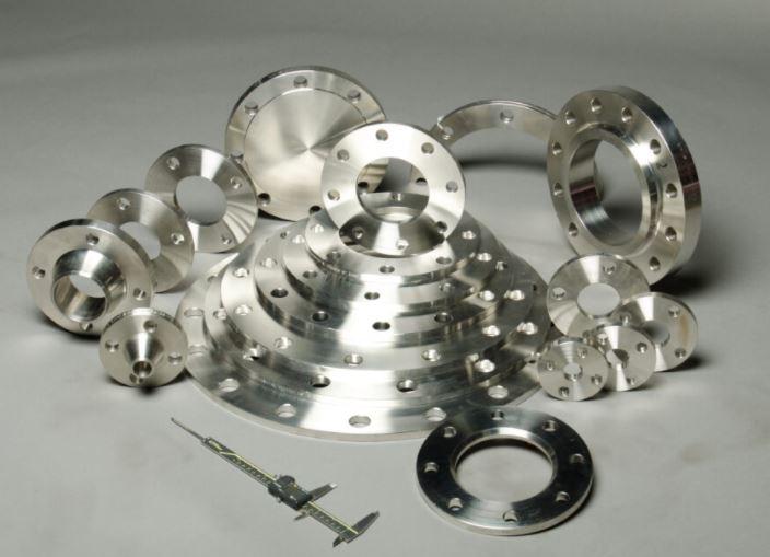
Dimensional Specifications for Weld Neck Flanges and Stud Bolts in ASME B16.5

The ASME B16.5 standard provides precisely defined dimensional requirements for weld neck flanges and associated bolting components to ensure interchangeability across manufacturers. Compliance with these specifications is important for ensuring flanges can withstand system pressures and join piping assemblies correctly in the field. This article examines some of the key dimensional parameters controlled by B16.5.
Weld Neck Flange Dimensions
B16.5 specifies minimum and maximum permissible dimensions for all aspects of Weld Neck Flanges geometry, including:
- Bolt hole diameter, count and spacing
- Flange face dimensions
- Weld neck bore and outside diameter
- Bolt circle diameter
- Flange and facing widths
Tight tolerances as small as ±1/64" ensure consistent dimensions to facilitate assembly regardless of manufacturer.

Stud Bolt Dimensions
To match standardized flange configurations, B16.5 also dictates stud bolt geometries including:
- Diameter, thread length and pitch
- Shank length matching flange thickness
- Head diameter and shape (heavy hex)
- Chemical and mechanical properties
Defining bolt dimensions prevents assembly issues and guarantees performance meeting rated pressure capabilities.
Pressure Class Variations
B16.5 defines 8 pressure classes from 150-2500 psi, with higher classes requiring increased:
- Flange thickness and material strength
- Bolt hole diameter and count for compressive load capacity
Dimensional requirements systematically scale based on pressure class to ensure structural integrity.
Non-Pressure Parts
Dimensions for non-pressure bearing items like bolt nuts are also standardized. Even small mounting hardware must strictly comply with standard outlines.
Precise industrial specifications like those found in ASME B16.5 are critical to ensuring reliability in piping systems. Consistent dimensional controls for weld neck flanges and associated hardware foster interchangeability across manufacturers and projects for decades of safe operation.
- Art
- Causes
- Crafts
- Dance
- Drinks
- Film
- Fitness
- Food
- Games
- Gardening
- Health
- Home
- Literature
- Music
- Networking
- Other
- Party
- Religion
- Shopping
- Sports
- Theater
- Wellness


